| Material | Application Scenario | Product and Process Feature Introduction | Remarks |
| 304 | Food Machinery and Equipment | Single weight: 6.83kg, food-grade 304 stainless steel, material must pass hazardous substance testing, surface fully machined | Tolerance accuracy of castings dimensional tolerance standard ISO8062 (GB/T6414) CT6 grade |
This screw shell is presented as a representative custom‑manufactured component for Food machinery and equipment Honyang Cast develops similar parts from customer drawings rather than offering a fixed catalog specification.
The manufacturing plan must connect the part's functional geometry—Geometry and functional interfaces to be confirmed from the customer drawing.—with tooling, investment casting, machining and measurable inspection requirements. Final dimensions, interfaces and acceptance criteria are confirmed during drawing review.
PROJECT‑SPECIFIC SUPPLY
Material grade, dimensions, tolerance zones, machining allowance, surface condition, operating requirements and inspection records are confirmed after review of the customer’s 2D drawing, 3D model and project specification.
The parameter set is selected for this component’s function. Unknown values remain drawing‑controlled and must not be replaced with generic catalog data.
| Engineering Item | Reference / Custom Requirement | Verification Basis |
|---|---|---|
| Material grade | 304; Page further calls it food‑grade 304 stainless steel | Confirm governing standard and chemistry requirements. |
| Part weight | 6.83 kg | Confirm target weight and allowable variation when relevant. |
| Functional geometry | To be confirmed from the customer drawing and project specification. | Identify drawing datums and critical‑to‑function features. |
| Casting / process reference | Surface fully machined | Confirm which steps apply to the quoted production route. |
| Dimensions and tolerances | To be confirmed from customer drawing. | Define casting tolerance separately from machined dimensions and GD&T. |
| Operating conditions | To be specified by customer. | Provide medium, load, temperature, pressure, speed or hygiene requirements as applicable. |
| Recommended additional fields | Add internal and external dimensions, machining allowance, roughness, material standard and fit requirements. | Complete before publishing numeric claims or quoting production. |
| Structural Feature | Why It Matters | Manufacturing Response |
|---|---|---|
| Drawing‑defined geometry and functional interfaces | This feature influences fit, flow, load transfer, manufacturability or downstream assembly. | Control profile geometry, section transitions, hub or mounting interfaces, and balance‑related features according to the approved drawing. |
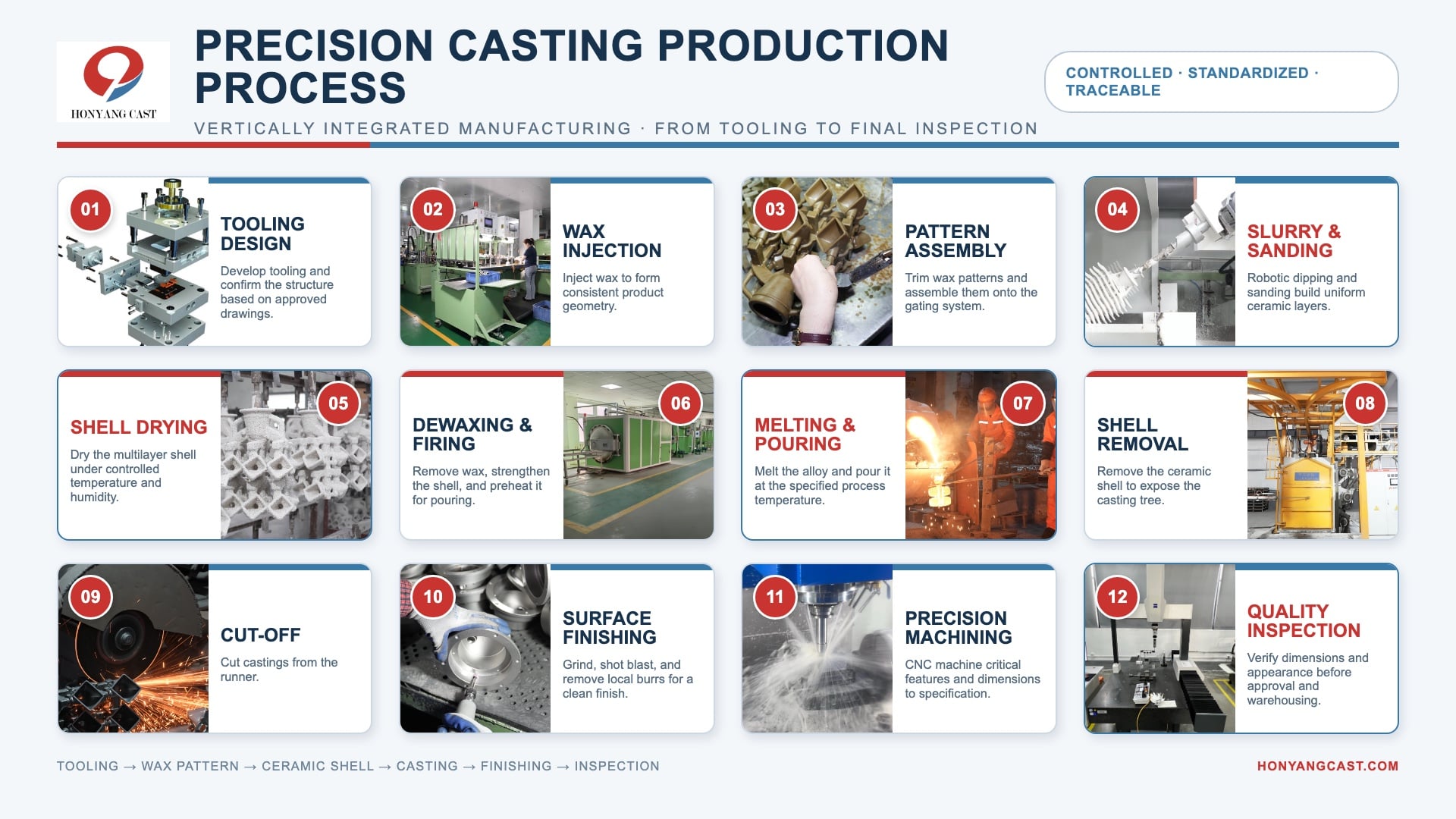
A project‑specific route is established after review of geometry, alloy, tolerance, volume and validation requirements.
Source Page Process References
PROCESS SCOPE
Investment casting and CNC machining are described as the core route. Heat treatment, coating, polishing, balancing, pressure testing, radiographic testing, PPAP or other special processes must be shown as project‑specific unless their scope is confirmed.
Honyang Cast supports drawing‑based development of screw shell and related investment cast components from manufacturability review through sample approval and repeat production.
| Application Requirement | Manufacturing Value |
|---|---|
| Drawing‑defined fit and function | A part‑specific DFM and inspection plan links casting geometry to the actual assembly and operating requirement. |
| Integrated complex geometry | Investment casting can consolidate features and reduce fabrication or excessive stock removal where the approved design supports it. |
| Repeatable critical interfaces | Controlled datums, machining and inspection support consistent assembly of functional surfaces and mating features. |
| Material and process traceability | Agreed material and inspection records provide evidence against the drawing and quality plan. |
| Product‑specific value | Confirm the exact screw/auger assembly and explain how the machined shell supports fit and cleanability. |
Design Inputs Required From the Customer
SEND YOUR DRAWING FOR A MANUFACTURABILITY REVIEW
Upload the drawing and 3D model for your main body of material discharge together with material, quantity, operating conditions and inspection requirements. Our team will review the casting route, machining scope and quality plan before quotation.

Leading manufacturer specializing in precision investment casting and CNC machining of high-performance steel components for critical industrial applications.
 EN